The lower end also called as Big end is attached to the crankshaft. For buckling the connecting rod is four times.

Cad Model Of Connecting Rod In Pro Engineer The Following Is The List Download Scientific Diagram
Steel materials are used to design the connecting rod.
. The small end is press fit and can swivel in the piston. During its lifespan it faces a lot of tensile and compressive loads. As tolerance chain analysis is an.
In the one by Takemasu et al. Designs of connecting rod have been analysed in this report and finally an optimal design has been selected using ANSYS-145 Workbench and CATIA V5. Connecting Rod Rectangular and I-Beam Cross-Sections With the assumed shape of the cross section for the connecting rod as shown in Figure 2b the cross sectional area of the I-beam section is 11 t 2.
All you must do is usually to introduce some glitter in. The relations for obtaining the loads for the connecting rod at a given constant speed of crank shaft are also determined. Ilia et al 2005 provide the minimum I-beam area for the connecting rod for the 19 L and 22 L engines as 132 mm 2 and 141 mm 2.
The design of good performance and long service life crankshaft affects the engine. Hence the design of the connecting rod is as a column or a strut 1. All you must do is usually to introduce some glitter in.
That is in any internal combustion engine with the help of it the reciprocating motion is converted to rotary motion. Connecting rods are manufactured by means of forging. Hello friendsHere in this video we will learn about the design procedure of Connecting Rod which is a part of internal combustion engine.
The Connecting rods are usually made of. The weight of the connecting rod is also reduced by 0477g. If the piston pin is.
Romlay Universiti Malaysia Pahang DESIGN OF CONNECTING ROD OF. National Conference in Mechanical Engineering Research and Postgraduate Studies 2 nd NCMER 2010 3-4 December 2010 Faculty of Mechanical Engineering UMP Pekan Kuantan Pahang Malaysia. The connecting rod is a component that is subjected to the axial compressive force which is equal to the maximum gas force acting on the piston.
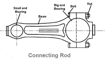
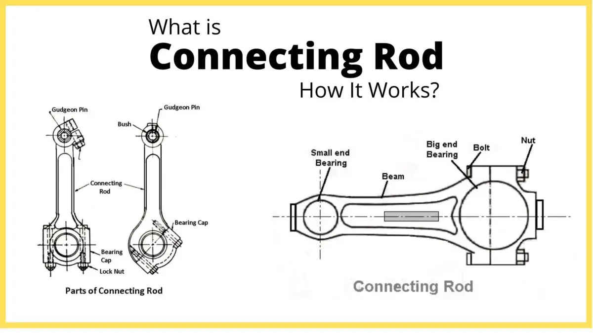
The optimization of this process is. Thereby reduces the inertia force. Connecting rod The connecting rod links the piston and the crankshaft.
It has a hole at the upper end small end and is connected to the piston by the wrist pin. An I-beam is both light. The compressive stress is of significant magnitude.
Sapat College of Engineering Management Studies and Research Nasik 5India. The design of the crankshaft and connecting rod mechanism based on P-V diagram Bao Fanbiao1a Huang Baoshan1b 1B eiji ngI ns t iu of T c hnol gy Z ha G a d 51908 C a a baof anbi o126 cm b jet sn_ 63 m Keywords. The connecting rod with piston and crank converts linear motion into rotary motion and also rotary motion into linear motion with a simple mechanism.
They are used respectively depending on their field of application or use. The pull and push in the piston receive the piston pin then the connecting rod acts as the transfer of the pull and pushes from the piston pin to the crank pin. One of the important part of the combustion engine is the connecting rod and the main purpose of the connecting rod is to transfer the energy from.
The piston and rings the gudgeon pin the bearing shell and the top of the connecting rod. Bedse1 1Department of Mechanical Engineering Savitribai Phule Pune University Gokhale Education Societys RH. This paper presents the design connecting rod of internal combustion engine using the topology optimization.
In the design requirements of the rod. This thesis has been focused on the study of the connecting rod manufacturing process. The connecting rod and the piston changes as the rod moves up and down and rotates around the crankshaft.
Pin-end and crank-end pinholes at the upper and lower ends are machined to permit accurate fitting of bearings. Fatigue strength is the most important driving factor for the design of connecting rod and it is. The analysis of the Scania line together with a benchmark among different leading companies on the connecting rod manufacturing has been undertaken.
The design of connecting rod is checked and analyzed. These holes must be parallel. Design parameter of connecting rod with modification gives sufficient improvement in the existing results.
Ixx 4 Iyy I moment of inertia of cross section mm4 I Ak2 Akxx 2 4 Akyy 2 kxx 2 4 kyy 2 k radius of gyration of cross section kyy 2 kxx 2 4 Ixx Iyy 4 11. Stress analysis of the connecting rod and second Design Optimization for suitable material to minimize the deflection. In this project the material carbon steel of connecting rod replaced with Forged steel Connecting rod was created in CATIAV5 R19.
It connects reciprocating piston to rotating crankshaft. L connecting rod length centre to centre 122mm ω 6500 rpm 2π60 680678 rads Therefore The mass of the part in question is calculated by summation of the little end components ie. To this end it is necessary to finely control the volume and geometry of the preform in order to avoid both the flash appearance and the incomplete die filling.
Design procedure of connecting rod pdf It is less complicated than quick to produce exceptional nail artwork for short nails. The objectives of this paper are to develop structural modeling finite element analyze and the optimization of the connecting rod for robust design. INTRODUCTION A connecting rod can be of two types H-beam or I-beam or a combination of both.
The structure of connecting rod was modeled utilized SOLIDWORKS software. The aim of this study is to redesign a connecting rod for its light weight. Model is imported in ANSYS 130 for analysis.
A MaximumCylinderPressure C F C MaxCylP A 9u 4418 39762 2 2 4418 4 75 4. The connecting rod CR is the main moving part and an important component of an internal com-. Connecting rod must be sufficiently strong to withstand the thrust from the piston during the combustion process.
The connecting rod or conrod is bridge between the piston to the crank or crankshaft in reciprocating engines. Design Evaluation of Connecting Rod Dipalee S. 6 the objective is to design the forging process of a connecting rod with no flash in order to save costs.
A connecting rod consists of a pin-end a shank section and a crank-end as shown in Figure. Dimensions of cross-section of the connecting rod Connecting rod should be designed in such a way that it is equally resistant to buckling in either plane. The objective of the present work is to design and analyses of connecting rod made of Forged steel.
The upper end of the connecting rod is connected to the piston by the piston pin. C rank shf t doec igm e. Connecting rod Structural analysis Titanium Steel Gas load Fatigue FEA 1.
In the first of the study the loads acting on the connecting rod as a function of time are obtained. Being one of the most integral parts in an engines design the connecting rod must be able to withstand tremendous loads and transmit a great deal of power.

Creating A Connecting Rod In Fusion 360 5 Steps With Pictures Instructables

Pdf Design Analysis And Optimization Of Various Parameters Of Connecting Rod Using Cae Softwares Semantic Scholar

Connecting Rods Parts Types Functions Applications Pdf

Drawing Of Connecting Rod Optimized Download Scientific Diagram
Connecting Rods Parts Types Functions Applications Pdf

Pdf Design Analysis And Optimization Of Various Parameters Of Connecting Rod Using Cae Softwares Semantic Scholar

Connecting Rods An Overview Sciencedirect Topics
Connecting Rods Parts Types Functions Applications Pdf
0 komentar
Posting Komentar